华为交换机M-LAG双归接入三层网络配置详解
在企业级网络架构中,高可靠性和高带宽利用率是核心诉求。M-LAG(Multi-Chassis Link Aggregation)作为一种跨设备链路聚合技术,可实现双归接入部署,既保证链路冗余备份,又能通过负载分担提升带宽利用率。本文将详细介绍基于V-STP方式的华为交换机M-LAG双归接入三层网络的完整配置方案,包含组网设计、配置步骤、验证方法及注意事项,适合网络工程师参考实践。
一、技术背景与组网需求
1. 核心优势
-
高可靠性:单条接入链路故障时,流量可快速切换至备用链路,无业务中断;
-
负载分担:两条链路同时处于Active状态,流量均匀分发,提升带宽利用率;
-
简化网络架构:通过双活网关设计,接入设备无需感知上行拓扑变化,降低配置复杂度。
2. 组网拓扑说明
本次配置涉及4台华为交换机,设备角色与接口对应关系如下: 本例中DeviceA的interface1、interface2、interface3、interface4、interface5和interface6分别代表100GE1/0/1,100GE1/0/2,100GE1/0/3,100GE1/0/4,100GE1/0/5和MEth0/0/0。
本例中DeviceB的interface1、interface2、interface3、interface4、interface5和interface6分别代表100GE1/0/1,100GE1/0/2,100GE1/0/3,100GE1/0/4,100GE1/0/5和MEth0/0/0。
本例中DeviceC的interface1和interface2分别代表100GE1/0/1和100GE1/0/2。 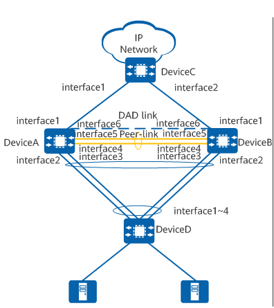
组网逻辑:DeviceA与DeviceB组成M-LAG双活节点,通过peer-link实现设备间协商;DeviceD通过Eth-Trunk双归接入DeviceA/B的M-LAG接口;DeviceA/B与DeviceC通过OSPF实现三层互通;启用V-STP避免接口阻塞,配置Monitor Link保障链路故障快速切换。
二、核心配置思路
配置接入设备DeviceD的上行Eth-Trunk,实现链路聚合;
在DeviceA/B上启用V-STP,创建DFS Group(双活组),配置peer-link和M-LAG接口;
配置DeviceA/B的VLANIF接口作为双活网关(统一虚拟IP和MAC);
部署OSPF协议,实现DeviceA/B/C之间的三层互通;
配置Monitor Link关联上下行接口,避免链路故障导致流量丢弃;
验证配置有效性,确保M-LAG状态正常、流量转发正常。
三、详细操作步骤
1. 基础准备
-
确保所有交换机固件版本一致;
-
规划网络地址:管理网段10.200.1.0/24,网关网段10.2.1.0/24,设备互联网段10.3.1.0/24、10.4.1.0/24;
-
规划VLAN:业务VLAN 11。
2. 配置DeviceD(接入设备)
核心需求:配置上行Eth-Trunk,绑定4个物理接口,实现与DeviceA/B的链路聚合。
<HUAWEI> system-view
[~HUAWEI] sysname DeviceD
[*HUAWEI] commit
[~DeviceD] vlan batch 11 # 创建业务VLAN
[*DeviceD] interface eth-trunk 20 # 创建Eth-Trunk接口
[*DeviceD-Eth-Trunk20] mode lacp-static # 静态LACP模式
[*DeviceD-Eth-Trunk20] port link-type trunk # trunk模式
[*DeviceD-Eth-Trunk20] port trunk allow-pass vlan 11 # 允许业务VLAN通过
[*DeviceD-Eth-Trunk20] trunkport 100ge 1/0/1 to 1/0/4 # 绑定物理接口
[*DeviceD-Eth-Trunk20] quit
[*DeviceD] commit # 提交配置
3. 配置DeviceA与DeviceB(M-LAG双活节点)
3.1 基础配置(V-STP+DFS Group+管理网口)
DeviceA配置:
<HUAWEI> system-view
[~HUAWEI] sysname DeviceA
[*HUAWEI] commit
[~DeviceA] stp mode rstp # 启用RSTP
[*DeviceA] stp v-stp enable # 启用V-STP
[*DeviceA] commit
[~DeviceA] interface meth 0/0/0 # 配置管理网口
[~DeviceA-MEth0/0/0] ip address 10.200.1.1 24
[*DeviceA-MEth0/0/0] quit
[*DeviceA] dfs-group 1 # 创建DFS Group
[*DeviceA-dfs-group-1] dual-active detection source ip 10.200.1.1 peer 10.200.1.2 # DAD检测
[*DeviceA-dfs-group-1] priority 150 # 优先级(150>120,成为Master)
[*DeviceA-dfs-group-1] authentication-mode hmac-sha256 password YsHsjx_202206 # 认证配置
[*DeviceA-dfs-group-1] quit
DeviceB配置(与DeviceA对称,仅IP和优先级不同):
<HUAWEI> system-view
[~HUAWEI] sysname DeviceB
[*HUAWEI] commit
[~DeviceB] stp mode rstp
[*DeviceB] stp v-stp enable
[*DeviceB] commit
[~DeviceB] interface meth 0/0/0
[~DeviceB-MEth0/0/0] ip address 10.200.1.2 24
[*DeviceB-MEth0/0/0] quit
[*DeviceB] dfs-group 1
[*DeviceB-dfs-group-1] dual-active detection source ip 10.200.1.2 peer 10.200.1.1
[*DeviceB-dfs-group-1] priority 120 # 优先级较低,成为Backup
[*DeviceB-dfs-group-1] authentication-mode hmac-sha256 password YsHsjx_202206
[*DeviceB-dfs-group-1] quit
3.2 配置peer-link与M-LAG接口
DeviceA配置:
[*DeviceA] interface eth-trunk 1 # 创建peer-link接口(设备间互联)
[*DeviceA-Eth-Trunk1] trunkport 100ge 1/0/4 to 1/0/5
[*DeviceA-Eth-Trunk1] mode lacp-static
[*DeviceA-Eth-Trunk1] peer-link 1 # 标记为peer-link
[*DeviceA-Eth-Trunk1] port vlan exclude 1 # 排除VLAN 1
[*DeviceA-Eth-Trunk1] quit
[*DeviceA] vlan batch 11
[*DeviceA] interface eth-trunk 10 # 创建M-LAG接口(对接DeviceD)
[*DeviceA-Eth-Trunk10] mode lacp-static
[*DeviceA-Eth-Trunk10] port link-type trunk
[*DeviceA-Eth-Trunk10] port trunk allow-pass vlan 11
[*DeviceA-Eth-Trunk10] trunkport 100ge 1/0/2 to 1/0/3
[*DeviceA-Eth-Trunk10] dfs-group 1 m-lag 1 # 绑定到DFS Group
[*DeviceA-Eth-Trunk10] quit
[*DeviceA] commit
DeviceB配置(与DeviceA完全一致):
[*DeviceB] interface eth-trunk 1
[*DeviceB-Eth-Trunk1] trunkport 100ge 1/0/4 to 1/0/5
[*DeviceB-Eth-Trunk1] mode lacp-static
[*DeviceB-Eth-Trunk1] peer-link 1
[*DeviceB-Eth-Trunk1] port vlan exclude 1
[*DeviceB-Eth-Trunk1] quit
[*DeviceB] vlan batch 11
[*DeviceB] interface eth-trunk 10
[*DeviceB-Eth-Trunk10] mode lacp-static
[*DeviceB-Eth-Trunk10] port link-type trunk
[*DeviceB-Eth-Trunk10] port trunk allow-pass vlan 11
[*DeviceB-Eth-Trunk10] trunkport 100ge 1/0/2 to 1/0/3
[*DeviceB-Eth-Trunk10] dfs-group 1 m-lag 1
[*DeviceB-Eth-Trunk10] quit
[*DeviceB] commit
3.3 配置双活网关(VLANIF)
DeviceA与DeviceB的VLANIF接口必须配置相同的IP和MAC,确保双活效果:
# DeviceA配置
[~DeviceA] interface vlanif 11
[*DeviceA-Vlanif11] ip address 10.2.1.1 24 # 虚拟网关IP
[*DeviceA-Vlanif11] mac-address 0000-5e00-0101 # 虚拟网关MAC
[*DeviceA-Vlanif11] quit
[*DeviceA] commit
# DeviceB配置(完全一致)
[~DeviceB] interface vlanif 11
[*DeviceB-Vlanif11] ip address 10.2.1.1 24
[*DeviceB-Vlanif11] mac-address 0000-5e00-0101
[*DeviceB-Vlanif11] quit
[*DeviceB] commit
3.4 配置OSPF实现三层互通
要求:DeviceA/B/C的OSPF区域0用于设备互联,区域1用于网关网段宣告。
DeviceA配置:
[~DeviceA] interface 100ge 1/0/1 # 对接DeviceC的接口
[~DeviceA-100GE1/0/1] undo portswitch # 切换为三层接口
[*DeviceA-100GE1/0/1] ip address 10.3.1.1 24
[*DeviceA-100GE1/0/1] quit
[*DeviceA] ospf 1
[*DeviceA-ospf-1] area 0 # 互联网段放入区域0
[*DeviceA-ospf-1-area-0.0.0.0] network 10.3.1.0 0.0.0.255
[*DeviceA-ospf-1-area-0.0.0.0] quit
[*DeviceA-ospf-1] area 1 # 网关网段放入区域1
[*DeviceA-ospf-1-area-0.0.0.1] network 10.2.1.0 0.0.0.255
[*DeviceA-ospf-1-area-0.0.0.1] quit
[*DeviceA-ospf-1] quit
[*DeviceA] commit
DeviceB配置:
[~DeviceB] interface 100ge 1/0/1
[~DeviceB-100GE1/0/1] undo portswitch
[*DeviceB-100GE1/0/1] ip address 10.4.1.1 24
[*DeviceB-100GE1/0/1] quit
[*DeviceB] ospf 1
[*DeviceB-ospf-1] area 0
[*DeviceB-ospf-1-area-0.0.0.0] network 10.4.1.0 0.0.0.255
[*DeviceB-ospf-1-area-0.0.0.0] quit
[*DeviceB-ospf-1] area 1
[*DeviceB-ospf-1-area-0.0.0.1] network 10.2.1.0 0.0.0.255
[*DeviceB-ospf-1-area-0.0.0.1] quit
[*DeviceB-ospf-1] quit
[*DeviceB] commit
DeviceC配置:
<HUAWEI> system-view
[~HUAWEI] sysname DeviceC
[*HUAWEI] commit
[~DeviceC] interface 100ge 1/0/1
[~DeviceC-100GE1/0/1] undo portswitch
[*DeviceC-100GE1/0/1] ip address 10.3.1.2 24 # 对接DeviceA
[*DeviceC-100GE1/0/1] quit
[*DeviceC] interface 100ge 1/0/2
[*DeviceC-100GE1/0/2] undo portswitch
[*DeviceC-100GE1/0/2] ip address 10.4.1.2 24 # 对接DeviceB
[*DeviceC-100GE1/0/2] quit
[*DeviceC] ospf 1
[*DeviceC-ospf-1] area 0
[*DeviceC-ospf-1-area-0.0.0.0] network 10.3.1.0 0.0.0.255
[*DeviceC-ospf-1-area-0.0.0.0] network 10.4.1.0 0.0.0.255
[*DeviceC-ospf-1-area-0.0.0.0] quit
[*DeviceC-ospf-1] quit
[*DeviceC] commit
3.5 配置Monitor Link
关联上行接口(对接DeviceC)和下行M-LAG接口,避免上行链路故障导致用户流量丢弃:
# DeviceA配置
[~DeviceA] monitor-link group 1
[*DeviceA-mtlk-group1] port 100ge 1/0/1 uplink # 上行接口
[*DeviceA-mtlk-group1] port eth-trunk 10 downlink 1 # 下行M-LAG接口
[*DeviceA-mtlk-group1] quit
[*DeviceA] commit
# DeviceB配置(完全一致)
[~DeviceB] monitor-link group 1
[*DeviceB-mtlk-group1] port 100ge 1/0/1 uplink
[*DeviceB-mtlk-group1] port eth-trunk 10 downlink 1
[*DeviceB-mtlk-group1] quit
[*DeviceB] commit
四、配置验证
1. 验证M-LAG状态
在DeviceA执行命令,查看DFS Group状态:
[~DeviceA] display dfs-group 1 m-lag
预期输出:
-
Heart beat state:OK(心跳正常)
-
DeviceA状态:Master(优先级150)
-
DeviceB状态:Backup(优先级120)
-
Causation:-(M-LAG建立成功)
2. 验证M-LAG接口状态
查看DeviceA/B的M-LAG接口状态:
# DeviceA
[~DeviceA] display dfs-group 1 node 1 m-lag brief
# DeviceB
[~DeviceB] display dfs-group 1 node 2 m-lag brief
预期输出:
-
Port State:Up(接口正常)
-
Status:active-active(双活状态)
-
Consistency-check:–(配置一致性正常)
3. 验证OSPF邻居与路由
在DeviceC查看OSPF邻居:
[~DeviceC] display ospf peer
预期:DeviceC与DeviceA、DeviceB均建立Full状态邻居。
查看路由表,确认10.2.1.0/24网段可达:
[~DeviceC] display ip routing-table
五、关键注意事项
双活网关一致性:DeviceA/B的VLANIF接口IP和MAC必须完全一致,否则双活失效;
V-STP配置:必须启用V-STP,避免接口因STP计算被阻塞,或关闭网络侧STP;
DFS Group认证:建议启用hmac-sha256认证,提升安全性;
接口绑定:peer-link建议绑定2个物理接口,提升可靠性;M-LAG接口成员数需与接入设备Eth-Trunk一致;
故障排查:若M-LAG状态异常,可通过display dfs-group 1 m-lag brief查看失败原因(如VLAN配置不一致、LACP模式不匹配等)。