1. 前言
在现代数据中心和园区网络的高可靠性设计中,M-LAG(Multichassis Link Aggregation Group,跨设备链路聚合组) 已经成为主流技术。它允许将两台物理交换机虚拟成一台逻辑交换机,从而实现跨设备的链路聚合。
本文将基于 ENSP Pro 模拟器,演示如何配置 M-LAG 双归接入三层网络。为了防止二层环路并优化拓扑,我们将采用 V-STP(虚拟生成树) 机制,确保 M-LAG 组在下游设备看来是一个单一的 STP 根桥。
功能实现
2. 拓扑信息
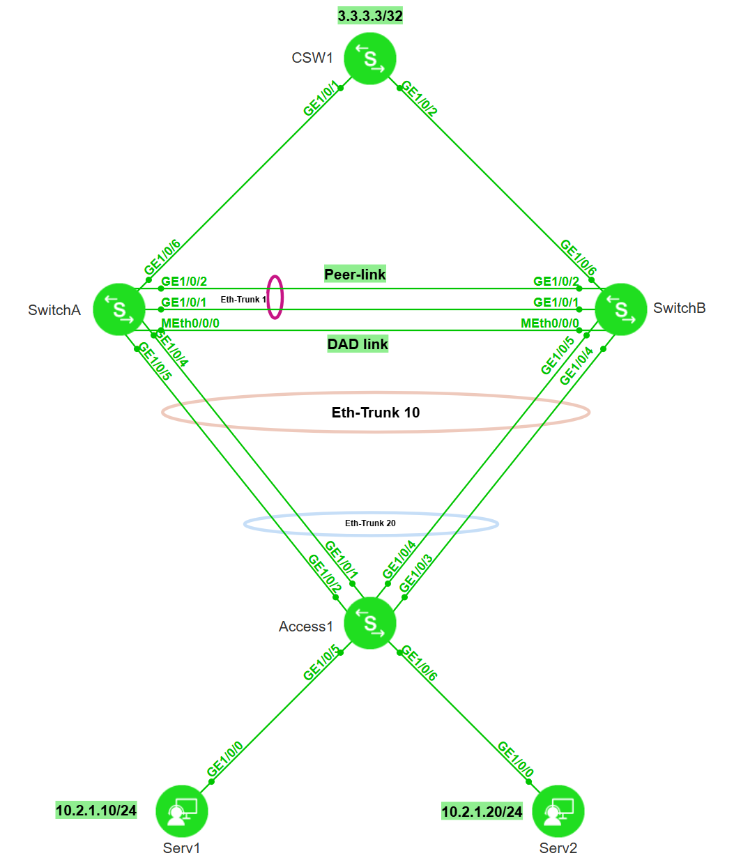
2.1 组网拓扑
- 核心交换机 (CSW1):模拟核心层,运行 OSPF,通过 Loopback 口模拟外部网络。
- M-LAG 设备 (SwitchA & SwitchB):模拟汇聚层,双活网关,运行 OSPF 上行,配置 V-STP 保证二层无环。
- 接入设备 (Access1):模拟接入层,通过 Eth-Trunk 双归接入 M-LAG 系统。
- 服务器 (Serv1 & Serv2):位于 VLAN 11,网关指向 M-LAG 的虚拟 IP。
2.2 关键配置参数表
| CSW1 | GE1/0/1 | IP: 10.3.1.2/24 | 连接 SwitchA |
| GE1/0/2 | IP: 10.4.1.2/24 | 连接 SwitchB | |
| Loopback0 | IP: 3.3.3.3/32 | 模拟外网测试地址 | |
| SwitchA | MEth0/0/0 | IP: 10.200.1.1/24 | DAD (Keepalive) 检测链路 |
| Eth-Trunk 1 | Peer-Link | 成员口: GE1/0/1, GE1/0/2 | |
| Eth-Trunk 10 | M-LAG 成员口 | 成员口: GE1/0/4, GE1/0/5 | |
| GE1/0/6 | IP: 10.3.1.1/24 | 上行连接 CSW1 | |
| Vlanif 11 | IP: 10.2.1.1/24 | 业务网关 (配置虚拟MAC) | |
| SwitchB | MEth0/0/0 | IP: 10.200.1.2/24 | DAD (Keepalive) 检测链路 |
| Eth-Trunk 1 | Peer-Link | 成员口: GE1/0/1, GE1/0/2 | |
| Eth-Trunk 10 | M-LAG 成员口 | 成员口: GE1/0/4, GE1/0/5 | |
| GE1/0/6 | IP: 10.4.1.1/24 | 上行连接 CSW1 | |
| Vlanif 11 | IP: 10.2.1.1/24 | 业务网关 (配置虚拟MAC) | |
| Access1 | Eth-Trunk 20 | 上行聚合 | 成员口: GE1/0/1-4 |
3. 组网需求与配置思路
3.1 组网需求
- M-LAG双归接入:SwitchA与SwitchB组成M-LAG系统,Access1通过双活链路接入。
- V-STP防环:在M-LAG系统上通过V-STP功能,将两台设备模拟成一台逻辑根桥,避免接入侧端口被STP阻塞。
- 双活网关:SwitchA与SwitchB配置相同的IP和MAC,作为下行设备的网关。
- Monitor Link联动:关联上行接口(连接核心路由)与下行M-LAG接口。当上行链路故障时,自动关闭下行接口,触发流量切换到对端M-LAG设备,防止流量丢弃。
- 三层互通:使用OSPF,且上行区域(Area 0)与下行网关区域(Area 1)分离。
3.2 配置思路
4. 操作步骤详解
第一步:配置接入层设备 (Access1)
接入设备只需将上行端口加入聚合组,无需感知M-LAG的存在。
Access1 配置:
[Access1]vlan batch 11
[Access1]int Eth-Trunk 20
[Access1-Eth-Trunk20]mode lacp-static
[Access1-Eth-Trunk20]port link-type trunk
[Access1-Eth-Trunk20]port trunk allow-pass vlan 11
[Access1-Eth-Trunk20]trunkport ge 1/0/1 to 1/0/4
[Access1-Eth-Trunk20]
第二步:配置 M-LAG 基础与 V-STP (SwitchA & SwitchB)
配置STP模式、开启V-STP、DFS Group认证及心跳、Peer-Link。
SwitchA 配置:
# 开启 V-STP
[SwitchA] stp mode rstp
[SwitchA] stp v-stp enable
# 配置 DAD 检测口
[SwitchA] interface meth 0/0/0
[SwitchA-MEth0/0/0] ip address 10.200.1.1 24
# 配置 DFS Group (含认证)
[SwitchA] dfs-group 1
[SwitchA-dfs-group-1] dual-active detection source ip 10.200.1.1 peer 10.200.1.2
[SwitchA-dfs-group-1] priority 150 # 主设备优先级高
# 配置 Peer-Link (Eth-Trunk 1)
[SwitchA] interface eth-trunk 1
[SwitchA-Eth-Trunk1] trunkport GE 1/0/1
[SwitchA-Eth-Trunk1] trunkport GE 1/0/2
[SwitchA-Eth-Trunk1] mode lacp-static
[SwitchA-Eth-Trunk1] peer-link 1
[SwitchA-Eth-Trunk1] port vlan exclude 1 # 最佳实践:剔除VLAN 1
SwitchB 配置:
# 开启 V-STP
[SwitchB] stp mode rstp
[SwitchB] stp v-stp enable
# 配置 DAD 检测口
[SwitchB] interface meth 0/0/0
[SwitchB-MEth0/0/0] ip address 10.200.1.2 24
# 配置 DFS Group
[SwitchB] dfs-group 1
[SwitchB-dfs-group-1] dual-active detection source ip 10.200.1.2 peer 10.200.1.1
[SwitchB-dfs-group-1] priority 120 # 备设备优先级低
# 配置 Peer-Link
[SwitchB] interface eth-trunk 1
[SwitchB-Eth-Trunk1] trunkport GE 1/0/1
[SwitchB-Eth-Trunk1] trunkport GE 1/0/2
[SwitchB-Eth-Trunk1] mode lacp-static
[SwitchB-Eth-Trunk1] peer-link 1
[SwitchB-Eth-Trunk1] port vlan exclude 1
第三步:配置 M-LAG 成员接口与业务网关
配置下行接口 Eth-Trunk 10,并配置分布式网关 VLANIF 11。
SwitchA 配置:
# 配置 M-LAG 成员口
[SwitchA] vlan batch 11
[SwitchA] interface eth-trunk 10
[SwitchA-Eth-Trunk10] mode lacp-static
[SwitchA-Eth-Trunk10] port link-type trunk
[SwitchA-Eth-Trunk10] port trunk allow-pass vlan 11
[SwitchA-Eth-Trunk10] trunkport GE 1/0/4
[SwitchA-Eth-Trunk10] trunkport GE 1/0/5
[SwitchA-Eth-Trunk10] dfs-group 1 m-lag 1
# 配置双活网关
[SwitchA] interface vlanif 11
[SwitchA-Vlanif10] ip address 10.2.1.1 24
[SwitchA-Vlanif10] mac-address 0000-5e00-0101 # 虚拟MAC
SwitchB 配置:
# 配置 M-LAG 成员口
[SwitchB] vlan batch 11
[SwitchB] interface eth-trunk 10
[SwitchB-Eth-Trunk10] mode lacp-static
[SwitchB-Eth-Trunk10] port link-type trunk
[SwitchB-Eth-Trunk10] port trunk allow-pass vlan 11
[SwitchB-Eth-Trunk10] trunkport GE 1/0/4
[SwitchB-Eth-Trunk10] trunkport GE 1/0/5
[SwitchB-Eth-Trunk10] dfs-group 1 m-lag 1
# 配置双活网关 (参数需与A完全一致)
[SwitchB] interface vlanif 11
[SwitchB-Vlanif10] ip address 10.2.1.1 24
[SwitchB-Vlanif10] mac-address 0000-5e00-0101
第四步:配置三层 OSPF 互通
注意区分区域:上行互联使用 Area 0,下行网关网段使用 Area 1。
CSW1 配置:
[CSW1] interface LoopBack0
[CSW1-LoopBack0] ip address 3.3.3.3 32
[CSW1] interface GE 1/0/1
[CSW1-GE1/0/1] undo portswitch
[CSW1-GE1/0/1] ip address 10.3.1.2 24 # 连接SwitchA
[CSW1] interface GE 1/0/2
[CSW1-GE1/0/2] undo portswitch
[CSW1-GE1/0/2] ip address 10.4.1.2 24 # 连接SwitchB
[CSW1] ospf 1 router-id 3.3.3.3
[CSW1-ospf-1] area 0.0.0.0
[CSW1-ospf-1-area-0.0.0.0] network 3.3.3.3 0.0.0.0
[CSW1-ospf-1-area-0.0.0.0] network 10.3.1.0 0.0.0.255 # 涵盖互联段
[CSW1-ospf-1-area-0.0.0.0] network 10.4.1.0 0.0.0.255 # 涵盖互联段
SwitchA OSPF 配置:
[SwitchA] interface GE 1/0/6
[SwitchA-GE1/0/6] undo portswitch
[SwitchA-GE1/0/6] ip address 10.3.1.1 24
[SwitchA] ospf 1 router-id 1.1.1.1
[SwitchA-ospf-1] area 0.0.0.0
[SwitchA-ospf-1-area-0.0.0.0] network 10.3.1.0 0.0.0.255 # 上行互联
[SwitchA-ospf-1] area 0.0.0.1
[SwitchA-ospf-1-area-0.0.0.1] network 10.2.1.0 0.0.0.255 # 下行网关
SwitchB OSPF 配置:
[SwitchB] interface GE 1/0/6
[SwitchB-GE1/0/6] undo portswitch
[SwitchB-GE1/0/6] ip address 10.4.1.1 24
[SwitchB] ospf 1 router-id 2.2.2.2
[SwitchB-ospf-1] area 0.0.0.0
[SwitchB-ospf-1-area-0.0.0.0] network 10.4.1.0 0.0.0.255 # 上行互联
[SwitchB-ospf-1] area 0.0.0.1
[SwitchB-ospf-1-area-0.0.0.1] network 10.2.1.0 0.0.0.255 # 下行网关
第五步:配置 Monitor Link (SwitchA & SwitchB)
这是关键的一步。将上行接口(GE1/0/6)定义为 uplink,下行 Eth-Trunk 10 定义为 downlink。当上行 GE 口 Down 时,自动强制 Eth-Trunk 10 Down,迫使流量走 SwitchB。
SwitchA 配置:
[SwitchA] monitor-link group 1
[SwitchA-mtlk-group1] port GE 1/0/6 uplink
[SwitchA-mtlk-group1] port eth-trunk 10 downlink 1
SwitchB 配置:
[SwitchB] monitor-link group 1
[SwitchB-mtlk-group1] port GE 1/0/6 uplink
[SwitchB-mtlk-group1] port eth-trunk 10 downlink 1
5. 结果验证
5.1 检查 M-LAG 状态
在 SwitchA 上执行:
[SwitchA]dis dfs-group 1 m-lag
* : Local node
Heart beat state : OK
Node 1 *
Dfs-Group ID : 1
Priority : 150
Dual-active Address : 10.200.1.1
VPN-Instance : public net
State : Master
Causation : –
System ID : fae8-d2bf-0011
SysName : SwitchA
Version : V600R024C10SPC500
Device Type : LSW
Node 2
Dfs-Group ID : 1
Priority : 120
Dual-active Address : 10.200.1.2
VPN-Instance : public net
State : Backup
Causation : –
System ID : fae8-d2bf-0021
SysName : SwitchB
Version : V600R024C10SPC500
Device Type : LSW
[SwitchA]
- Heart beat state: OK
- Node State: Master
- Causation: – (建立成功)
在 SwitchA 上查看详细接口状态:
[SwitchA]dis dfs-group 1 node 1 m-lag brief
* – Local node
M-Lag ID Interface Mode Port State Status Consistency-check
1 Eth-Trunk 10 active-active Up active(*)-active —
Failed reason:
1 — Relationship between vlan and port is inconsistent
2 — STP configuration under the port is inconsistent
3 — STP port priority configuration is inconsistent
4 — LACP mode of M-LAG is inconsistent
5 — M-LAG configuration is inconsistent
6 — The number of M-LAG members is inconsistent
7 — LACP system-id of M-LAG is inconsistent
8 — LACP priority of M-LAG is inconsistent
9 — STP port edged configuration is inconsistent
10 — M-LAG mode configuration is inconsistent
11 — VCMP configuration on the port is inconsistent
12 — LINK-TYPE configuration on the port is inconsistent
[SwitchA]
- Local Status: active
- Remote Status: active
- Port State: Up
5.2 检查 OSPF 路由
在 CSW1 上查看路由表,应能看到去往 10.2.1.0/24 的路由有两条(负载分担):
[CSW1]dis ip routing-table 10.2.1.0
Proto: Protocol Pre: Preference
Route Flags: R – relay, D – download to fib, T – to vpn-instance, B – black hole route
——————————————————————————
Routing Table : _public_
Summary Count : 2
Destination/Mask Proto Pre Cost Flags NextHop Interface
10.2.1.0/24 OSPF 10 2 D 10.4.1.1 GE1/0/2
OSPF 10 2 D 10.3.1.1 GE1/0/1
[CSW1]
5.3 Monitor Link 测试
[SwitchA-GE1/0/6]shutdown
[SwitchA]dis int eth-trunk 10
Eth-Trunk10 current state : ERROR DOWN(monitor-link) (ifindex: 17)
Line protocol current state : DOWN
Description:
Switch Port, PVID : 1, TPID : 8100(Hex), Hash Arithmetic : src-dst-ip, Maximal BW : 2Gbps, Current BW : 0Mbps, The Maximum Frame Length is 9216
Internet protocol processing : disabled
IP Sending Frames' Format is PKTFMT_ETHNT_2, Hardware address is fae8-d2bf-0011
Current system time: 2026-01-25 10:01:16
Physical is ETH_TRUNK
Last 300 seconds input rate 253 bits/sec, 0 packets/sec
Last 300 seconds output rate 434 bits/sec, 0 packets/sec
Input: 4966 packets,671255 bytes
10 unicast,2205 broadcast,2751 multicast
0 errors,0 drops
Output:12311 packets,1315104 bytes
10 unicast,2205 broadcast,10096 multicast
0 errors,0 drops
Last 300 seconds input utility rate: 0.00%
Last 300 seconds output utility rate: 0.00%
———————————————————-
PortName Status Weight
———————————————————-
GE1/0/4 DOWN 1
GE1/0/5 DOWN 1
———————————————————-
The Number of Ports in Trunk : 2
The Number of Up Ports in Trunk : 0
[SwitchA]
6. 关键配置
SwitchA
sysname SwitchA
stp mode rstp
stp v-stp enable
#
dfs-group 1
priority 150
dual-active detection source ip 10.200.1.1 peer 10.200.1.2
#
vlan batch 11
#
interface MEth0/0/0
ip address 10.200.1.1 255.255.255.0
#
interface Eth-Trunk1
mode lacp-static
peer-link 1
port vlan exclude 1
trunkport GE 1/0/1
trunkport GE 1/0/2
#
interface Eth-Trunk10
port link-type trunk
port trunk allow-pass vlan 11
mode lacp-static
dfs-group 1 m-lag 1
trunkport GE 1/0/4
trunkport GE 1/0/5
#
interface Vlanif11
ip address 10.2.1.1 255.255.255.0
mac-address 0000-5e00-0101
#
interface GE1/0/6
undo portswitch
ip address 10.3.1.1 255.255.255.0
#
monitor-link group 1
port GE1/0/6 uplink
port Eth-Trunk10 downlink 1
#
ospf 1 router-id 1.1.1.1
area 0.0.0.0
network 10.3.1.0 0.0.0.255
area 0.0.0.1
network 10.2.1.0 0.0.0.255
SwitchB
sysname SwitchB
stp mode rstp
stp v-stp enable
#
dfs-group 1
priority 120
dual-active detection source ip 10.200.1.2 peer 10.200.1.1
#
vlan batch 11
#
interface MEth0/0/0
ip address 10.200.1.2 255.255.255.0
#
interface Eth-Trunk1
mode lacp-static
peer-link 1
port vlan exclude 1
trunkport GE 1/0/1
trunkport GE 1/0/2
#
interface Eth-Trunk10
port link-type trunk
port trunk allow-pass vlan 11
mode lacp-static
dfs-group 1 m-lag 1
trunkport GE 1/0/4
trunkport GE 1/0/5
#
interface Vlanif11
ip address 10.2.1.1 255.255.255.0
mac-address 0000-5e00-0101
#
interface GE1/0/6
undo portswitch
ip address 10.4.1.0 255.255.255.0
#
monitor-link group 1
port GE1/0/6 uplink
port Eth-Trunk10 downlink 1
#
ospf 1 router-id 2.2.2.2
area 0.0.0.0
network 10.4.1.0 0.0.0.255
area 0.0.0.1
network 10.2.1.0 0.0.0.255