一、实验背景与需求
企业网络要求业务不中断,需要解决链路单点故障、网关单点故障、二层环路、静态路由维护麻烦问题。 实验需求:
二、拓扑与 IP 规划
拓扑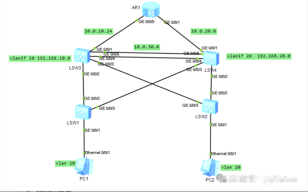
- 核心:LSW3、LSW4;接入:LSW1、LSW2;出口路由器 AR1
- PC1 属于 VLAN10:192.168.10.10/24,虚拟网关 192.168.10.254
- PC2 属于 VLAN20:192.168.20.10/24,虚拟网关 192.168.20.254
互联网段
表格
| AR1‑LSW3 | 10.0.10.0/24 |
| AR1‑LSW4 | 10.0.20.0/24 |
| LSW3‑LSW4 聚合 | 10.0.30.0/24 |
MSTP 规划
- Instance1 映射 VLAN10,LSW3 为主根桥,LSW4 备份
- Instance2 映射 VLAN20,LSW4 为主根桥,LSW3 备份
VRRP 规划
- VLAN10:LSW3 优先级 120(主),LSW4 优先级 100(备),虚拟 IP:192.168.10.254
- VLAN20:LSW4 优先级 120(主),LSW3 优先级 100(备),虚拟 IP:192.168.20.254
链路聚合:LSW3 与 LSW4 之间 GE0/0/4、GE0/0/5,模式 lacp‑static
三、完整配置脚本
LSW3 配置
system-view
sysname LSW3
vlan batch 10 20
#链路聚合Eth‑Trunk1
interface Eth‑Trunk 1
mode lacp-static
port link-type trunk
port trunk allow-pass vlan 10 20
interface GigabitEthernet 0/0/4
eth‑trunk 1
interface GigabitEthernet 0/0/5
eth‑trunk 1
#对接AR1
interface GigabitEthernet 0/0/1
port link-type trunk
port trunk allow-pass vlan 10 20
#对接接入LSW1
interface GigabitEthernet 0/0/2
port link-type trunk
port trunk allow-pass vlan 10 20
#MSTP配置
stp mode mstp
stp region-configuration
region-name MST‑TEST
instance 1 vlan 10
instance 2 vlan 20
active
stp instance 1 root primary
stp instance 2 root secondary
#三层VLANIF接口
interface Vlanif 10
ip address 192.168.10.1 255.255.255.0
interface Vlanif 20
ip address 192.168.20.1 255.255.255.0
interface Vlanif 1
ip address 10.0.10.2 255.255.255.0
#VRRP
interface Vlanif 10
vrrp vrid 10 virtual‑ip 192.168.10.254
vrrp vrid 10 priority 120
interface Vlanif 20
vrrp vrid 20 virtual‑ip 192.168.20.254
vrrp vrid 20 priority 100
#OSPF
ospf 1 router-id 3.3.3.3
area 0
network 192.168.10.0 0.0.0.255
network 192.168.20.0 0.0.0.255
network 10.0.10.0 0.0.0.255
LSW4 配置
system-view
sysname LSW4
vlan batch 10 20
#链路聚合
interface Eth‑Trunk 1
mode lacp-static
port link-type trunk
port trunk allow-pass vlan 10 20
interface GigabitEthernet 0/0/4
eth‑trunk 1
interface GigabitEthernet 0/0/5
eth‑trunk 1
#对接AR1
interface GigabitEthernet 0/0/1
port link-type trunk
port trunk allow-pass vlan 10 20
#对接LSW2
interface GigabitEthernet 0/0/2
port link-type trunk
port trunk allow-pass vlan 10 20
#MSTP区域配置必须和LSW3完全一致
stp mode mstp
stp region-configuration
region-name MST‑TEST
instance 1 vlan 10
instance 2 vlan 20
active
stp instance 2 root primary
stp instance 1 root secondary
#三层接口
interface Vlanif 10
ip address 192.168.10.2 255.255.255.0
interface Vlanif 20
ip address 192.168.20.2 255.255.255.0
interface Vlanif 1
ip address 10.0.20.2 255.255.255.0
#VRRP
interface Vlanif 10
vrrp vrid 10 virtual‑ip 192.168.10.254
vrrp vrid 10 priority 100
interface Vlanif 20
vrrp vrid 20 virtual‑ip 192.168.20.254
vrrp vrid 20 priority 120
#OSPF
ospf 1 router-id 4.4.4.4
area 0
network 192.168.10.0 0.0.0.255
network 192.168.20.0 0.0.0.255
network 10.0.20.0 0.0.0.255
LSW1 接入交换机
system-view
sysname LSW1
vlan batch 10
#上联
interface GigabitEthernet 0/0/2
port link-type trunk
port trunk allow-pass vlan 10
#下联PC
interface Ethernet 0/0/1
port link-type access
port default vlan 10
#MSTP,区域参数必须一致
stp mode mstp
stp region-configuration
region-name MST‑TEST
instance 1 vlan 10
instance 2 vlan 20
active
LSW2 接入交换机
system-view
sysname LSW2
vlan batch 20
interface GigabitEthernet 0/0/2
port link-type trunk
port trunk allow-pass vlan 20
interface Ethernet 0/0/1
port link-type access
port default vlan 20
stp mode mstp
stp region-configuration
region-name MST‑TEST
instance 1 vlan 10
instance 2 vlan 20
active
AR1 路由器
system-view
sysname AR1
interface GigabitEthernet 0/0/0
ip address 10.0.10.1 255.255.255.0
interface GigabitEthernet 0/0/1
ip address 10.0.20.1 255.255.255.0
ospf 1 router-id 1.1.1.1
area 0
network 10.0.10.0 0.0.0.255
network 10.0.20.0 0.0.0.255
四、PC 参数
- PC1:IP 192.168.10.10,掩码255.255.255.0,网关192.168.10.254
- PC2:IP 192.168.20.10,掩码255.255.255.0,网关192.168.20.254
五、验证排错命令
#查看链路聚合状态
display eth‑trunk 1
#查看MSTP生成树状态
display stp brief
display stp region‑configuration
#查看VRRP主备状态
display vrrp brief
#OSPF邻居与路由表
display ospf peer brief
display ip routing-table