深度缓冲(Depth Buffering)
目录
目录
深度缓冲(Depth Buffering)
目录
简介(Introduction)
3D 几何体(3D geometry)
额外的正方形(extra square)
深度问题(depth issues)
深度图像与视图(Depth image and view)
命令缓冲区(Command buffer)
清除值(Clear values)
动态渲染(Dynamic rendering)
显式转换深度图像布局(Explicitly transitioning the depth image)
深度和模板状态(Depth and stencil state)
深度正确显示(depth correct)
处理窗口大小调整(Handling window resize)
相关代码
简介(Introduction)
到目前为止,我们处理的几何体虽被投影到 3D 空间,但仍完全是平面的。在本章中,我们将为顶点位置添加 Z 坐标,为渲染 3D 网格做准备。我们会利用这个第三个坐标,在当前正方形上方放置另一个正方形,以此展示几何体未按深度排序时出现的问题。
3D 几何体(3D geometry)
修改 Vertex 结构体,将位置改为 3D 向量,并更新对应的 vk::VertexInputAttributeDescription 中的格式:
struct Vertex {
glm::vec3 pos;
glm::vec3 color;
glm::vec2 texCoord;
…
static std::array<vk::VertexInputAttributeDescription, 3> getAttributeDescriptions() {
return {
vk::VertexInputAttributeDescription(0, 0, vk::Format::eR32G32B32Sfloat, offsetof(Vertex, pos)),
vk::VertexInputAttributeDescription(1, 0, vk::Format::eR32G32B32Sfloat, offsetof(Vertex, color)),
vk::VertexInputAttributeDescription(2, 0, vk::Format::eR32G32Sfloat, offsetof(Vertex, texCoord))
};
…
}
};
接下来,修改顶点着色器,将输入的 inPosition 类型从 float2 改为 float3,以接收并变换 3D 坐标:
struct VSInput {
float3 inPosition;
…
};
…
[shader("vertex")]
VSOutput vertMain(VSInput input) {
VSOutput output;
output.pos = mul(ubo.proj, mul(ubo.view, mul(ubo.model, float4(input.inPosition, 1.0))));
output.fragColor = input.inColor;
output.fragTexCoord = input.inTexCoord;
return output;
}
记得修改后重新编译着色器!
最后,更新顶点容器,添加 Z 坐标:
const std::vector<Vertex> vertices = {
{{-0.5f, -0.5f, 0.0f}, {1.0f, 0.0f, 0.0f}, {0.0f, 0.0f}},
{{0.5f, -0.5f, 0.0f}, {0.0f, 1.0f, 0.0f}, {1.0f, 0.0f}},
{{0.5f, 0.5f, 0.0f}, {0.0f, 0.0f, 1.0f}, {1.0f, 1.0f}},
{{-0.5f, 0.5f, 0.0f}, {1.0f, 1.0f, 1.0f}, {0.0f, 1.0f}}
};
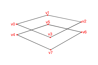
如果现在运行应用程序,你会看到和之前完全相同的结果。接下来,我们添加一些额外的几何体,让场景更丰富,同时演示本章要解决的问题。复制现有顶点,在当前正方形正下方定义另一个正方形的位置,如下所示:
额外的正方形(extra square)
将 Z 坐标设为 -0.5f,并为这个额外的正方形添加对应的索引:
const std::vector<Vertex> vertices = {
{{-0.5f, -0.5f, 0.0f}, {1.0f, 0.0f, 0.0f}, {0.0f, 0.0f}},
{{0.5f, -0.5f, 0.0f}, {0.0f, 1.0f, 0.0f}, {1.0f, 0.0f}},
{{0.5f, 0.5f, 0.0f}, {0.0f, 0.0f, 1.0f}, {1.0f, 1.0f}},
{{-0.5f, 0.5f, 0.0f}, {1.0f, 1.0f, 1.0f}, {0.0f, 1.0f}},
{{-0.5f, -0.5f, -0.5f}, {1.0f, 0.0f, 0.0f}, {0.0f, 0.0f}},
{{0.5f, -0.5f, -0.5f}, {0.0f, 1.0f, 0.0f}, {1.0f, 0.0f}},
{{0.5f, 0.5f, -0.5f}, {0.0f, 0.0f, 1.0f}, {1.0f, 1.0f}},
{{-0.5f, 0.5f, -0.5f}, {1.0f, 1.0f, 1.0f}, {0.0f, 1.0f}}
};
const std::vector<uint16_t> indices = {
0, 1, 2, 2, 3, 0,
4, 5, 6, 6, 7, 4
};
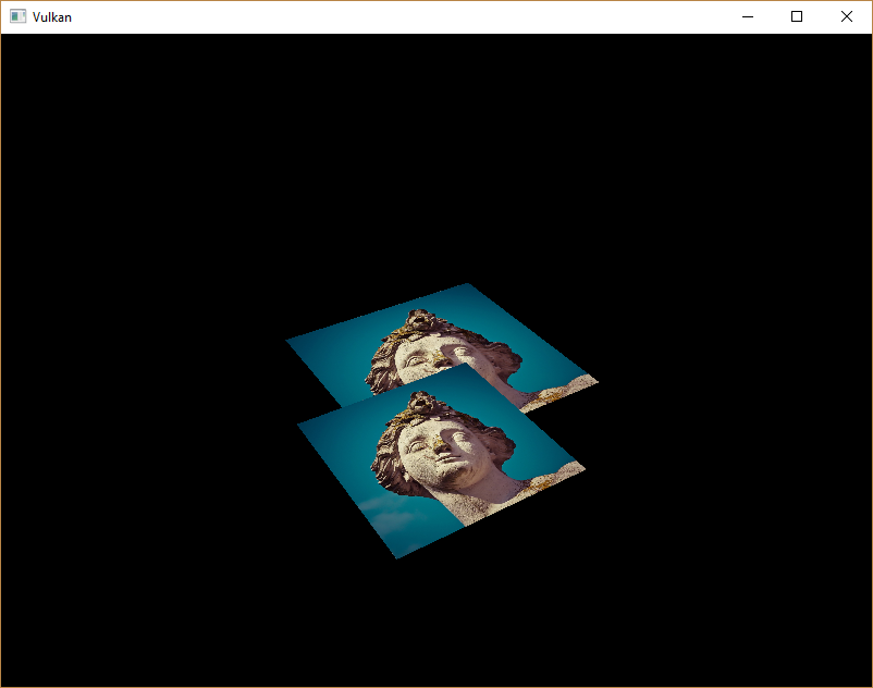
现在运行程序,你会看到类似Escher illustration:
深度问题(depth issues)
问题在于,下方正方形的片段会覆盖上方正方形的片段 —— 原因很简单,只是因为它在索引数组中出现得更晚。有两种解决方法:
- 按深度从后到前对所有绘制调用排序
- 使用深度缓冲区(depth buffer)进行深度测试(depth testing)
第一种方法通常用于绘制透明物体,因为 “顺序无关透明”(order-independent transparency)是一个难以解决的难题。但对于按深度排序片段的问题,更常用的解决方案是深度缓冲区。深度缓冲区是一种附加的帧缓冲区附件,它像颜色附件存储每个像素的颜色一样,存储每个像素位置的深度值。每当光栅化器生成一个片段时,深度测试会检查这个新片段是否比之前的片段更近。如果不是,新片段就会被丢弃;通过深度测试的片段会将自身的深度值写入深度缓冲区。你可以像操作颜色输出一样,在片段着色器中修改这个深度值。
添加以下代码,调整 GLM 透视投影矩阵的深度范围:
#define GLM_FORCE_DEPTH_ZERO_TO_ONE
#include <glm/glm.hpp>
#include <glm/gtc/matrix_transform.hpp>
GLM 生成的透视投影矩阵默认使用 OpenGL 的深度范围(-1.0 到 1.0)。我们需要通过定义 GLM_FORCE_DEPTH_ZERO_TO_ONE,将其配置为使用 Vulkan 的深度范围(0.0 到 1.0)。
深度图像与视图(Depth image and view)
深度附件和颜色附件一样,都是基于图像(image)的。不同之处在于,交换链不会自动为我们创建深度图像。我们只需要一个深度图像,因为同一时间只会运行一个绘制操作。深度图像同样需要三类资源:图像(image)、内存(memory)和图像视图(image view)。
添加类成员变量存储深度图像相关资源:
vk::raii::Image depthImage = nullptr;
vk::raii::DeviceMemory depthImageMemory = nullptr;
vk::raii::ImageView depthImageView = nullptr;
创建新函数 createDepthResources 来初始化这些资源:
void initVulkan() {
…
createCommandPool();
createDepthResources();
createTextureImage();
…
}
…
void createDepthResources() {
}
创建深度图像的流程相当直接:它应具有与颜色附件相同的分辨率(由交换链的 extent 定义)、适合深度附件的图像用途(image usage)、最优平铺(optimal tiling)模式,且分配在设备本地内存(device local memory)中。唯一需要确定的是:深度图像的正确格式是什么?该格式必须包含深度分量,在 vk::Format 中以 D?? 标识。
与纹理图像不同,我们不一定需要特定的格式(因为不会从程序中直接访问其纹理像素),只需保证合理的精度即可 —— 实际应用中,至少 24 位是常见标准。以下几种格式符合该要求:
- vk::Format::eD32Sfloat:32 位浮点型深度分量
- vk::Format::eD32SfloatS8Uint:32 位有符号浮点型深度分量 + 8 位模板(stencil)分量
- vk::Format::eD24UnormS8Uint:24 位归一化浮点型深度分量 + 8 位模板分量
模板分量用于模板测试(stencil tests),这是一种可与深度测试结合使用的附加测试,我们将在后续章节介绍。
我们本可以直接使用 vk::Format::eD32Sfloat(其支持率极高,可参考硬件数据库),但尽可能为应用程序增加灵活性会更好。我们将编写一个 findSupportedFormat 函数:它接收一个候选格式列表(按从最理想到最不理想排序),并返回第一个受支持的格式:
vk::Format findSupportedFormat(const std::vector<vk::Format>& candidates, vk::ImageTiling tiling, vk::FormatFeatureFlags features) {
}
格式的支持性取决于平铺模式(tiling mode)和用途,因此这些也需作为参数传入。可通过 physicalDevice.getFormatProperties 函数查询格式的支持性:
for (const auto format : candidates) {
vk::FormatProperties props = physicalDevice.getFormatProperties(format);
}
vk::FormatProperties 结构体包含三个字段:
- linearTilingFeatures:线性平铺(linear tiling)模式下支持的用途
- optimalTilingFeatures:最优平铺(optimal tiling)模式下支持的用途
- bufferFeatures:作为缓冲区使用时支持的用途
此处仅前两个字段相关,具体检查哪一个取决于函数的 tiling 参数:
if (tiling == vk::ImageTiling::eLinear && (props.linearTilingFeatures & features) == features) {
return format;
}
if (tiling == vk::ImageTiling::eOptimal && (props.optimalTilingFeatures & features) == features) {
return format;
}
如果没有候选格式支持所需用途,可返回特殊值或直接抛出异常:
vk::Format findSupportedFormat(const std::vector<vk::Format>& candidates, vk::ImageTiling tiling, vk::FormatFeatureFlags features) {
for (const auto format : candidates) {
vk::FormatProperties props = physicalDevice.getFormatProperties(format);
if (tiling == vk::ImageTiling::eLinear && (props.linearTilingFeatures & features) == features) {
return format;
}
if (tiling == vk::ImageTiling::eOptimal && (props.optimalTilingFeatures & features) == features) {
return format;
}
}
throw std::runtime_error("failed to find supported format!");
}
现在,我们用这个函数创建 findDepthFormat 辅助函数,选择一个包含深度分量且支持作为深度附件使用的格式:
VkFormat findDepthFormat() {
return findSupportedFormat(
{vk::Format::eD32Sfloat, vk::Format::eD32SfloatS8Uint, vk::Format::eD24UnormS8Uint},
vk::ImageTiling::eOptimal,
vk::FormatFeatureFlagBits::eDepthStencilAttachment
);
}
注意,此处需使用 vk::FormatFeatureFlagBits,而非 vk::ImageUsageFlagBits。这些候选格式都包含深度分量,但后两种还包含模板分量 —— 我们暂时不会使用模板分量,但在对这类格式的图像进行布局转换时,必须将其考虑在内。添加一个简单的辅助函数,判断所选深度格式是否包含模板分量:
bool hasStencilComponent(vk::Format format) {
return format == vk::Format::eD32SfloatS8Uint || format == vk::Format::eD24UnormS8Uint;
}
在 createDepthResources 中调用该函数,找到合适的深度格式:
vk::Format depthFormat = findDepthFormat();
现在,我们已有所有必要信息,可调用 createImage 和 createImageView 辅助函数:
createImage(swapChainExtent.width, swapChainExtent.height, depthFormat, vk::ImageTiling::eOptimal, vk::ImageUsageFlagBits::eDepthStencilAttachment, vk::MemoryPropertyFlagBits::eDeviceLocal, depthImage, depthImageMemory);
depthImageView = createImageView(depthImage, depthFormat, vk::ImageAspectFlagBits::eDepth);
但当前 createImageView 函数默认子资源的 aspect 是 vk::ImageAspectFlagBits::eColor,因此需要将该字段改为参数:
vk::raii::ImageView createImageView(vk::raii::Image& image, vk::Format format, vk::ImageAspectFlags aspectFlags) {
…
vk::ImageViewCreateInfo viewInfo{
…
.subresourceRange = {aspectFlags, 0, 1, 0, 1}};
…
}
更新所有调用该函数的地方,传入正确的 aspect:
swapChainImageViews[i] = createImageView(swapChainImages[i], swapChainImageFormat, vk::ImageAspectFlagBits::eColor);
…
depthImageView = createImageView(depthImage, depthFormat, vk::ImageAspectFlagBits::eDepth);
…
textureImageView = createImageView(textureImage, vk::Format::eR8G8B8A8Srgb, vk::ImageAspectFlagBits::eColor);
深度图像的创建至此完成。我们无需映射它,也无需向其复制其他图像 —— 因为会在命令缓冲区开始时,像清理颜色附件一样清理它。
命令缓冲区(Command buffer)
清除值(Clear values)
由于现在有多个需要以 vk::AttachmentLoadOp::eClear 方式清除的附件(颜色和深度),因此也需要指定多个清除值。进入 recordCommandBuffer 函数,创建并添加一个名为 clearDepth 的 vk::ClearValue 变量:
vk::ClearValue clearColor = vk::ClearColorValue(0.0f, 0.0f, 0.0f, 1.0f);
vk::ClearValue clearDepth = vk::ClearDepthStencilValue(1.0f, 0);
在 Vulkan 中,深度缓冲区的深度范围是 0.0 到 1.0—— 其中 1.0 对应远裁剪面(far view plane),0.0 对应近裁剪面(near view plane)。深度缓冲区中每个位置的初始值应设为最大可能深度,即 1.0。
动态渲染(Dynamic rendering)
深度图像已配置完成,现在需要在 recordCommandBuffer 中使用它。这是动态渲染(dynamic rendering)的一部分,与配置颜色输出图像的流程类似。
首先,为深度图像指定新的渲染附件:
vk::RenderingAttachmentInfo depthAttachmentInfo = {
.imageView = depthImageView,
.imageLayout = vk::ImageLayout::eDepthAttachmentOptimal,
.loadOp = vk::AttachmentLoadOp::eClear,
.storeOp = vk::AttachmentStoreOp::eDontCare,
.clearValue = clearDepth};
并将其添加到动态渲染信息结构体中:
vk::RenderingInfo renderingInfo = {
…
.pDepthAttachment = &depthAttachmentInfo};
显式转换深度图像布局(Explicitly transitioning the depth image)
和颜色附件一样,深度附件也需要处于适合其用途的布局。为此,我们需要发出额外的屏障(barriers),确保深度图像在渲染期间能作为深度附件使用。深度图像首先在 “早期片段测试”(early fragment test)管线阶段被访问,且由于我们的加载操作是清除(clear),因此应指定写入对应的访问掩码(access mask)。
由于现在要处理新的图像类型(深度),首先为 transition_image_layout 函数添加一个 image aspect 参数:
void transition_image_layout(
…
vk::ImageAspectFlags image_aspect_flags)
{
vk::ImageMemoryBarrier2 barrier = {
…
.subresourceRange = {
.aspectMask = image_aspect_flags,
.baseMipLevel = 0,
.levelCount = 1,
.baseArrayLayer = 0,
.layerCount = 1}};
}
然后,在 recordCommandBuffer 的命令缓冲区起始位置,添加新的图像布局转换:
commandBuffers[currentFrame].begin({});
// 颜色附件的布局转换
transition_image_layout(
…
vk::ImageAspectFlagBits::eColor);
// 深度图像的新布局转换
transition_image_layout(
*depthImage,
vk::ImageLayout::eUndefined,
vk::ImageLayout::eDepthAttachmentOptimal,
vk::AccessFlagBits2::eDepthStencilAttachmentWrite,
vk::AccessFlagBits2::eDepthStencilAttachmentWrite,
vk::PipelineStageFlagBits2::eEarlyFragmentTests | vk::PipelineStageFlagBits2::eLateFragmentTests,
vk::PipelineStageFlagBits2::eEarlyFragmentTests | vk::PipelineStageFlagBits2::eLateFragmentTests,
vk::ImageAspectFlagBits::eDepth);
与颜色图像不同,此处无需多个屏障 —— 因为帧结束后我们不关心深度附件的内容,因此始终可以从 vk::ImageLayout::eUndefined 转换。该布局的特殊之处在于:无论之前的状态如何,都可以将其作为源布局使用。
同时,确保调整所有其他对 transition_image_layout 的调用,传入正确的图像 aspect:
// 开始渲染前,将交换链图像转换为 COLOR_ATTACHMENT_OPTIMAL 布局
transition_image_layout(
…
// 颜色图像也需指定该参数
vk::ImageAspectFlagBits::eColor);
深度和模板状态(Depth and stencil state)
深度附件已准备就绪,但仍需在图形管线中启用深度测试。这通过 PipelineDepthStencilStateCreateInfo 结构体配置:
vk::PipelineDepthStencilStateCreateInfo depthStencil{
.depthTestEnable = vk::True,
.depthWriteEnable = vk::True,
.depthCompareOp = vk::CompareOp::eLess,
.depthBoundsTestEnable = vk::False,
.stencilTestEnable = vk::False};
- depthTestEnable:指定是否应将新片段的深度与深度缓冲区比较,以决定是否丢弃该片段
- depthWriteEnable:指定通过深度测试的片段,其深度值是否应写入深度缓冲区
- depthCompareOp:指定用于保留 / 丢弃片段的比较操作。我们遵循 “深度值越小,距离越近” 的惯例,因此新片段的深度应小于现有值
- depthBoundsTestEnable、minDepthBounds、maxDepthBounds:用于可选的深度范围测试(depth bound test),仅保留深度值在指定范围内的片段。本教程不使用该功能
- 最后三个字段用于配置模板缓冲区操作(stencil buffer operations),本教程也不涉及。若要使用这些操作,需确保深度 / 模板图像的格式包含模板分量
如果动态渲染配置中包含深度模板附件,则必须指定深度模板状态:
更新 pipelineCreateInfoChain 结构体链,引用我们刚填充的深度模板状态,并添加对所用深度格式的引用:
vk::StructureChain<vk::GraphicsPipelineCreateInfo, vk::PipelineRenderingCreateInfo> pipelineCreateInfoChain = {
{.stageCount = 2,
…
.pDepthStencilState = &depthStencil,
…
{.colorAttachmentCount = 1, .pColorAttachmentFormats = &swapChainSurfaceFormat.format, .depthAttachmentFormat = depthFormat}};
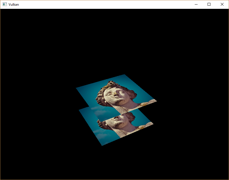
现在运行程序,你会看到几何体的片段已按深度正确排序:
处理窗口大小调整(Handling window resize)
当窗口大小调整时,深度缓冲区的分辨率应随之改变,以匹配新的颜色附件分辨率。扩展 recreateSwapChain 函数,在窗口调整时重新创建深度资源:
void recreateSwapChain() {
int width = 0, height = 0;
while (width == 0 || height == 0) {
glfwGetFramebufferSize(window, &width, &height);
glfwWaitEvents();
}
device.waitIdle(device);
cleanupSwapChain();
createSwapChain();
createImageViews();
createDepthResources();
}
恭喜!你的应用程序现在终于能够渲染任意 3D 几何体,并正确显示其深度关系了。在下一章中,我们将通过绘制带纹理的模型来验证这一功能!